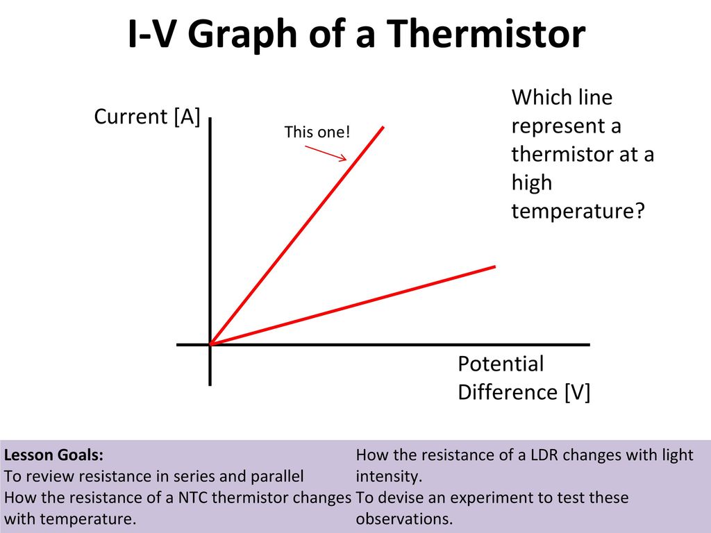
Thermistor iv graph
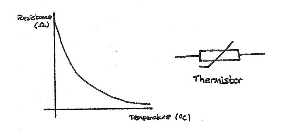
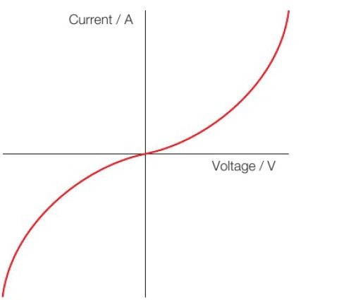
I-V graph for Thermistor For the thermistor its resistance reduces with the temperature. What is IV characteristics of.

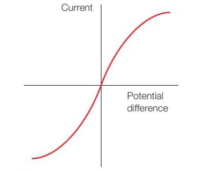
Voltage Current Graphs S Cool The Revision Website
Thermistors Color Chart.

. Thermistor Iv Graph The Student Room Build and Run the Application. 16 rows Motor Protection Thermistors. Their resistance decreases as the light intensity increases.
Thermistors change in resistance is non-linear. Tb transition temperature. This chart compares the tolera nce differences between an interchangeable thermistor and two point-matched thermistors.
Thermistor graphs and LDR graphs will always be straight lines through origin like a fixed resistor. Overall they are typically identified by their resistive capacity at 25. It follows a pre-defined curve which is provided by the thermistor manufacturer.
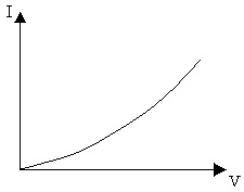
This VI defaults to the Voltage Reference mode. Light dependent resistors or LDRs. An example of a thermistor output curve can be seen in Figure 1.
ABB Motor Fans and Covers. In case of Thermistor at higher voltage range when current flow. Series FIP54 VVP MPMPS Fan Series 3000 Ring and Clamp.
I-V Graphs for LDR and Thermistor GCSE Physics Edexcel. 7biv no current no ammeter reading and diode has been reversed diode does not conduct has very high. The thermistor is used for measuring the small range of temperature between -55C and 114C whereas the RTD measures the temperature up to 850ºC.
SENSOR RESISTANCE CHART PRECON THERMISTORS PRECON TYPE II PRECON TYPE III PRECON TYPE IV Model 21 Model 22 Model 24 Model 27 Model 3 Model 42 2252Ω 77F. Temperature graph shows how a PTC reacts to temperature changes. Are made of semiconductor.
The I-V graph of metallic conductor is a straight line pass through the origin. Convert Thermistor Reading waveform Type of Excitation distinguishes the two modes of operation of the VI. The temperature where the ceramic microstructure changes.
Apart from the two distinct categories of NTC and PTC thermistor types differ by curve and range. I think thats right after reading the thread so to answer the OP. The I-V graph for a diode LDRs and thermistors.
They obey Ohms Law having resistance that is independent of current. The resistance above this point is. The blue lines show the.

Ohm S Law Pass My Exams Easy Exam Revision Notes For Gsce Physics

Mr Toogood Physics Resistors And Resistance
Current Electricity Revise Im
Starter Stick In The Following In The Right Places Ppt Download
2

Aqa Gcse Physics Electricity Iv Graphs Flashcards Quizlet

Ohm S Law Pass My Exams Easy Exam Revision Notes For Gsce Physics
How To Identify I V Graph Of A Thermistor I V Graph Of A Filament Bulb

I V Graphs Youtube
I V Graph Of Thermistor Mini Physics Learn Physics
I V Graphs Explained Thermistors And Ldrs Gcse Science Physics Get To Know Science Youtube
Thermistor Iv Graph The Student Room

Current Voltage Characteristics Ohmic Conductor Semiconductor Diode Filament Lamp And Ohm S Law

Current Voltage Characteristics Ohmic Conductor Semiconductor Diode Filament Lamp And Ohm S Law
How To Identify I V Graph Of A Thermistor I V Graph Of A Filament Bulb
Thermistor Iv Graph The Student Room

Current Voltage Characteristics Ohmic Conductor Semiconductor Diode Filament Lamp And Ohm S Law